СмартПульс
- держите руку на пульсе высоких технологий!
Новости, статьи, обзоры мобильных устройств, компьютеров, комплектующих, радиолюбительских конструкций
СмартПульс
- держите руку на пульсе высоких технологий!
Новости, статьи, обзоры мобильных устройств, компьютеров, комплектующих, радиолюбительских конструкций
СмартПульс
- держите руку на пульсе высоких технологий!
Новости, статьи, обзоры мобильных устройств, компьютеров, комплектующих, радиолюбительских конструкций
Main (Ru) - DIY (Ru) - Dual-channel audio power amplifier XH-M543 (2x50W) class D chip TPA3116D2 - test and user review
|
Dual-channel audio power
amplifier XH-M543 (2x50W) class D chip TPA3116D2 - test and user review The review is devoted to a single-Board audio power amplifier (UHF) class D XH-M543 2x50 watts. On AliExpress, this amplifier is often advertised by many sellers as 2x100 Watts and even as 2x120 Watts. Do not believe it: the "main" chip of the amplifier a power of 2x50 W, and no more. But even this is a great power! The review below contains technical characteristics of the IC stereo amplifier, briefly describes the circuit design of the tested single-Board amplifier, shows oscillograms of the amplifier and provides some useful insights.
All waveforms are photographed from the screen of an analog oscilloscope with a cathode ray tube as it does not have a fixed frame rate, so it allows to better track the dynamics of processes than a digital oscilloscope. TPA3116D2 chip specifications:
Note: All features and a typical connection diagram TPA3116D2 specified in the Datasheet TPA3116D2 (PDF, 1.4 Mb). One of important technical features of the chip is the possiblility to connect it in single-channel mode; then its output power becomes 1 x 100 watts. But this configuration requires appropriate changes in the external elements and the PCB. The tested version of the amplifier has no "flexible" configuration and is designed to operate strictly in two-channel mode.
The price
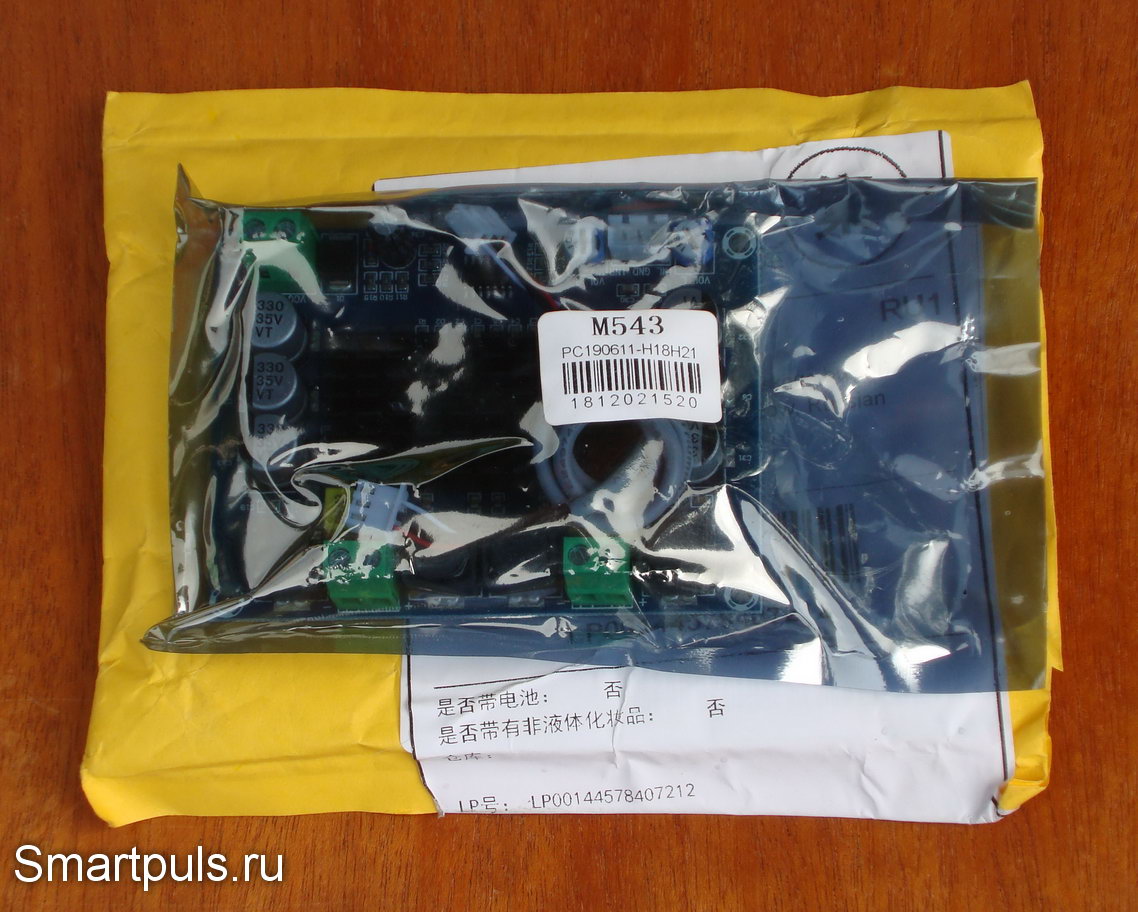
at the time of the review - about $7. Appearance and design of two-channel (stereo) amplifier D-class XH-M543 on chip TPA3116D2 The amplifier was packaged in a sealed anti-static bag, further wrapped in several layers of bubble wrap (photo not shown):
The packaging protects the amplifier Board well enough from possible "adventures" on the way. The package contained an amplifier Board and a 30 cm (12 inches) long cable to connect to the signal source:
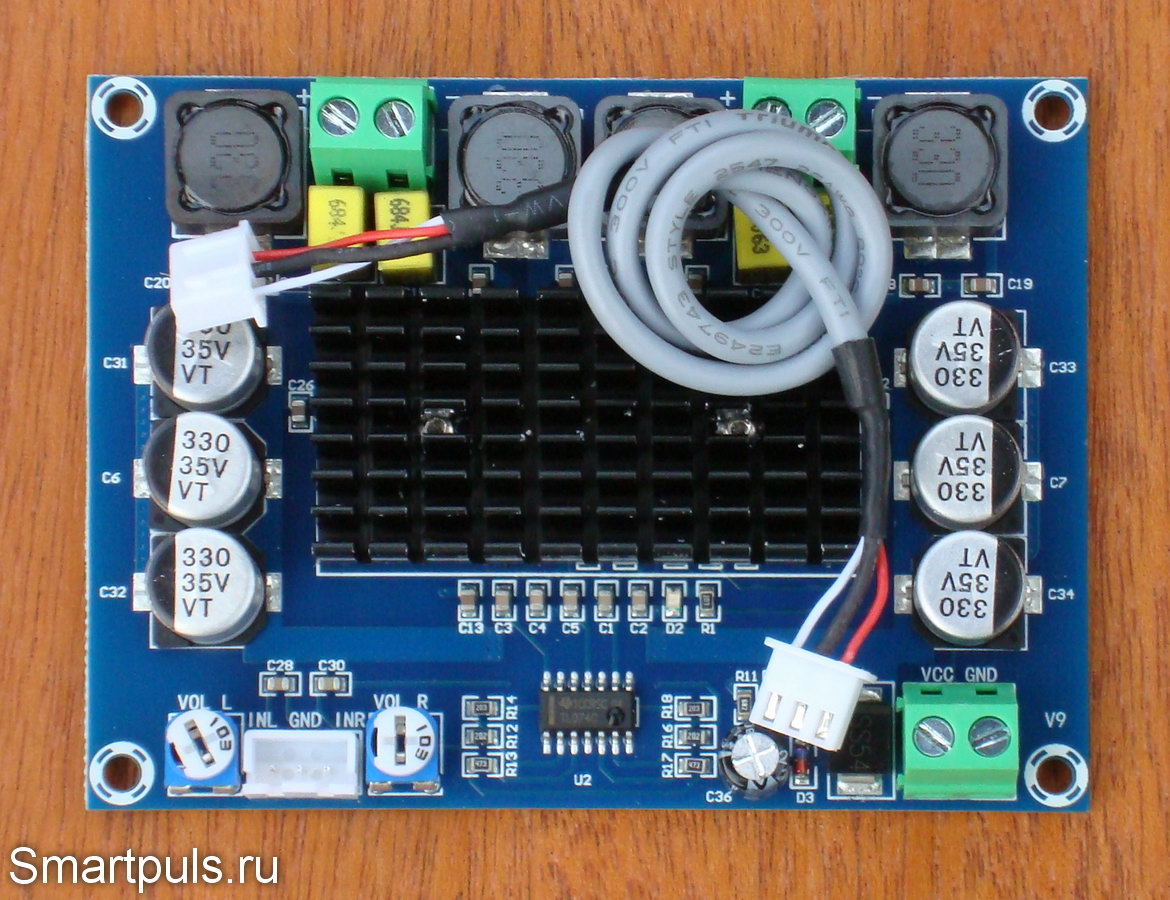
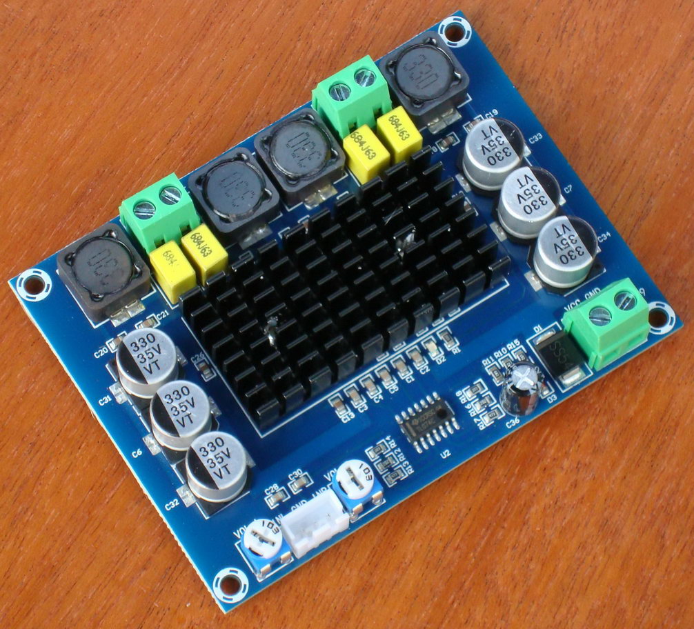
No documentation was included, and it is not needed: the Board indicates the purpose of contacts. Also, the connection diagram of the Board is available on the amplifier page in AliExpress. Here are some pictures from different angles:
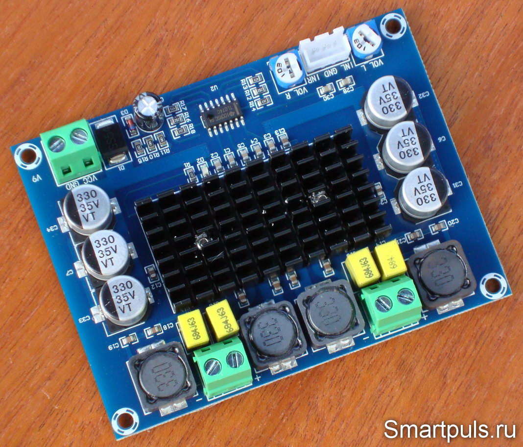
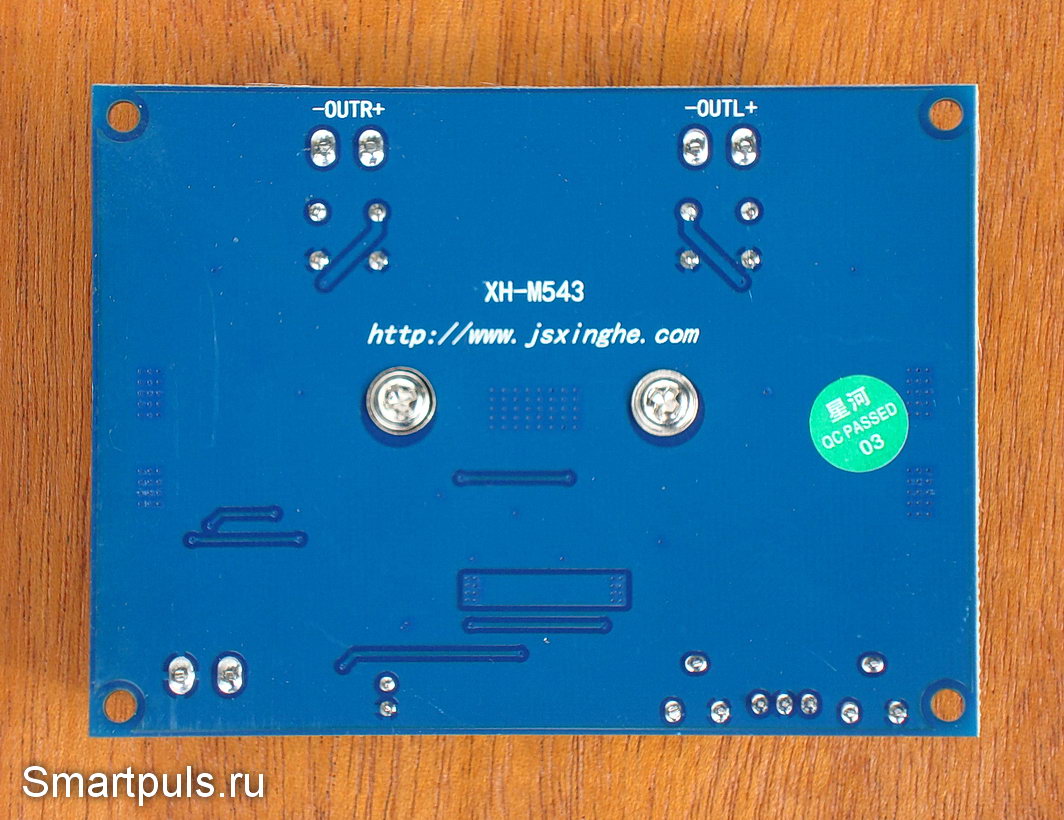
All external connections are made without soldering - using screw terminals and connector. The holes for mounting the Board are in the corners. Let's look at the reverse side of the Board:
The reverse side of the Board is almost completely covered with metallization layer with a ground connection. This is very useful for anti-interference. You can also see the heads of the two screws that fasten the heat sink to the TPA3116D2 chip. The Board also has a link to the manufacturer's website.
The site is in Chinese, some titles are translated into
English.
The site is "heavy" and works slowly. Circuitry dual-channel (stereo) amplifier D-class XH-M543 chip TPA3116D2 To analyze the circuitry, remove the heat sink from the Board and look at the Board with the elements as it is:
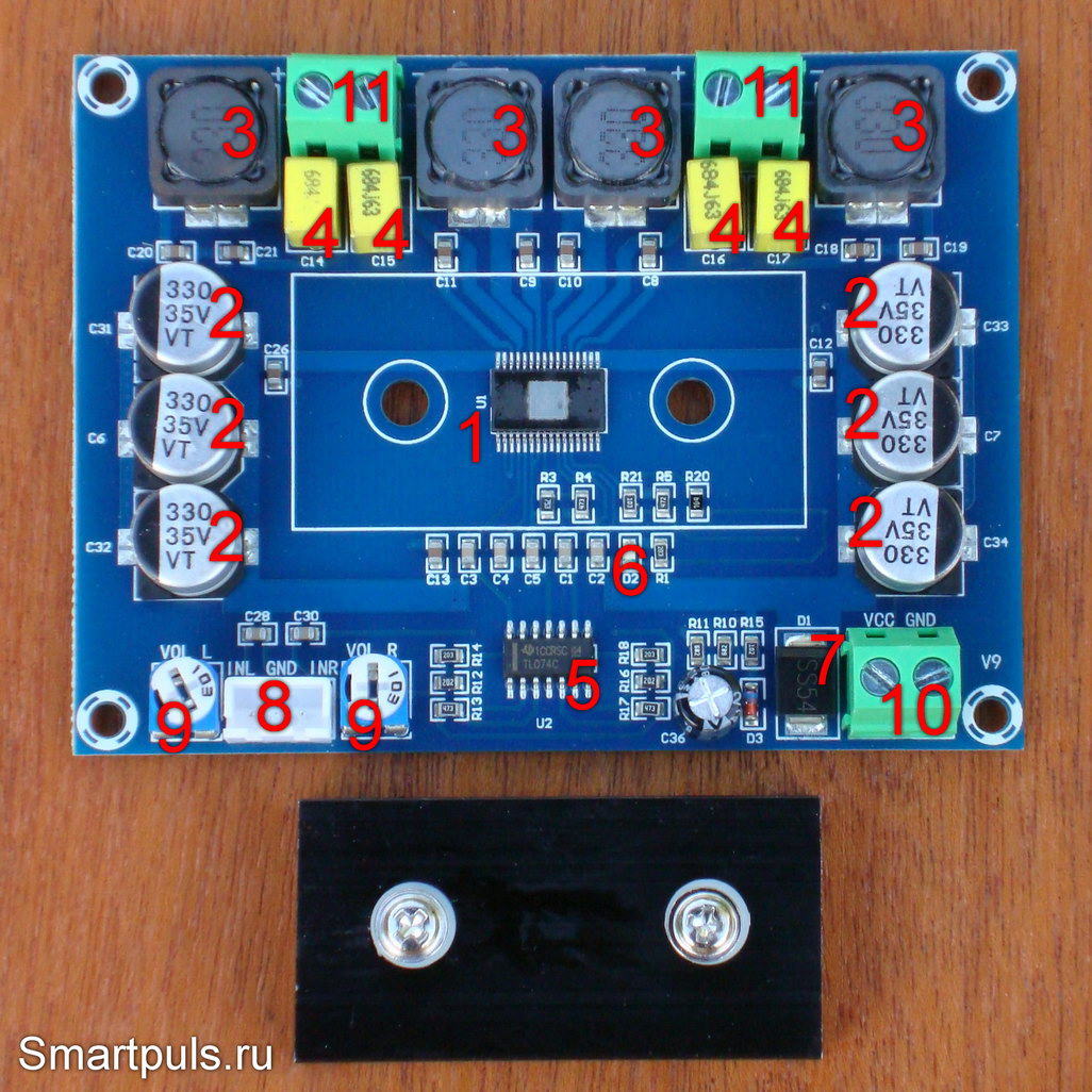
Let's start with the heatsink. The heat sink radiator has a blackened surface, including the point of contact with the chip. This worsens the thermal contact. It is preferable to carefully clean off the blackening from the bottom of the heat sink without leaving deep furrows, and add thermal grease. Initially, some light liquid was used instead of thermal paste; probably, engine oil. Anyway, if you do not intend to use the amplifier at maximum power for a long time, you can leave it as it is. When removing the heat sink, try not to lose the plastic washers on the screws located between the radiator and the PCB. They serve to align the position of the radiator to lay down on the chip without skewing. Now let's examine the main elements of the Board. 1- Chip amplifier TPA3116D2. 2 - Blocking electrolytes in power supply circuits. It is great that there are many of them; they also seem to be of high quality (with polymer electrolyte); and not forever flowing and exploding standard liquid electrolytic capacitors. 3 - Chokes output LC-filters. The nominal value is 33 µg, although the datasheet of the TPA3116D2 chip recommends 10 µg. Might be better, since the PWM oscillator frequency is here set to the minimum of the number of possible frequencies for the TPA3116D2. 4 - Capacitors output LC-filters. The rate of the capacitors (0.68 UF) exactly corresponds to the recommendations in the description (datasheet) on the chip. 5 - Operational amplifier in the pre-amplification circuit, type TL074C (four amplifiers in a single package), TL074 datasheet (PDF, 110 Kb). 6 - Power indication led. Shines a dim but noticeable blue when powered. 7 - Safety diode to protect from the polarity of the power supply. In this capacity, the Schottky diode SS 54 is used, characterized by a small voltage drop when the current flows in the forward direction (very good!), datasheet of a Schottky diode SS54 (PDF, 410 Kb). 8 - Connector for connecting the input signal via the supplied cable. 9 - Trimmer resistors to adjust the input signal level (separately for the left and right channel). 10 - Terminal block for power connection (screw clip for bare wire). 11 - Terminal blocks for connection of amplifier outputs.
In conclusion, we must say that the circuitry and design of the
amplifier is built correctly and as close as possible to the
recommendations in the technical description (datasheet) for the chip
TPA3116D2. Installation and soldering of parts on the Board is done
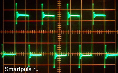
carefully. Testing of d-class audio power amplifier on TPA3116D2 chip The measurements used a power supply from a Toshiba laptop with a voltage of 19 Volts and a current of up to 6.3 amperes (120 W). Unfortunately, the voltage is slightly less than the 21 Volts required for maximum power according to the technical description TPA3116D2. Another source with a similar capacity, unfortunately, was not at hand. :( When testing for maximum sinusoidal power, only one channel was loaded (in order to avoid overheating and failure of the amplifier); more on this at the end of the review. In other cases both channels were loaded. The no-load current consumption (no signal) was 35 mA without load connection and changed by less than 1 mA when a 4 Ohm load was connected to both channels. This indicates a good balance of zero at the amplifier output. You can further read about a series of successive experiments with the supply of a sinusoidal signal and a gradual increase in power. The output signal to the oscilloscope was taken from one of the arms of the amplifier (left channel output +). Before the output filter of the amplifier, a rectangular signal was observed, as it should be according to the theory of class D amplifiers. There were also short-term "emissions", apparently due to the "ringing" in the filter (which is acceptable):
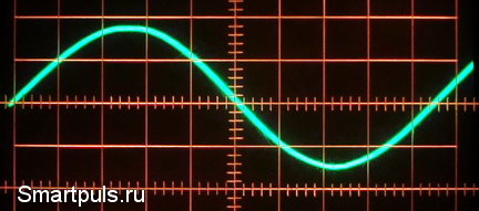
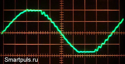
The PWM oscillator frequency was 400 kHz, the minimum of the possible frequencies for the tpa3116d2 chip. The minimum frequency does not mean that it is bad, it is a circuit feature. At any signal levels below the clipping voltage, we observe an almost perfect sine at the output. No interference with the PWM oscillator frequency to the output passes; that is, the filters work very well:
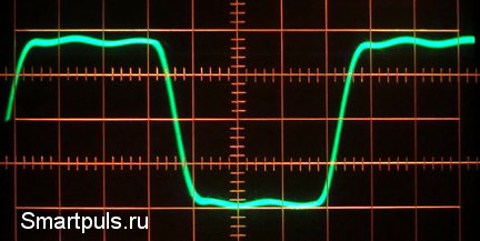
With a further increase in the signal level comes clipping, as it should be on the theory. During clipping on the waveform is visible "ringing" filters (frequency sinusoidal signal 1 kHz):
Clipping is observed almost perfectly symmetrical both "top" and" bottom " (good). The frequency of "ringing" after clipping is at the limit of audibility of the human ear, so it is unlikely that it will be somehow noticeable against the background of distortions caused by clipping itself. With a further increase in the signal, we observe a picture approaching the rectangle, but with the "ringing" described above (the frequency of the sinusoidal signal is 6.3 kHz):
Now we’ll talk about the other properties of the amplifier. The amplitude-frequency response (AFC) of the amplifier has some peculiarities. In the low-pass region, the minus 3 dB bandwidth starts at 46 Hz (not 20 Hz, as should be the case with Hi-Fi equipment). Thus, we note the "early" decline in frequency response in the low frequencies. The decline in the low frequencies can be partially corrected by "external" means if available (tone control or equalizer). In the region of high frequencies even more interesting effects are observed. If the output is connected to a conventional passive (ohmic) load, the bandwidth at the level of -3 dB ends at 12.5 kHz; and at the frequency of 20 kHz, the drop is already 2 times (-6 dB). But, if you do not connect any load (idle), there is no drop, and the growth of the output signal; the component at a frequency of 20 kHz 1.75 times! And finally, the last option is to connect a high-frequency speaker as a load. In this case, at the frequency of 20 kHz there is a small increase in the signal by 5%. Finally, we take the frequency band of the amplifier from 46 Hz to 20 kHz, as the closest to the real conditions. Heating of the amplifier even in single-channel mode at maximum sinusoidal power is essential. The heating heat sink was about 50-60 degrees °С (120...140°F), and the heating of the protective diode exceeded 60 degrees °С (140°F). At the same time, when listening to a real signal (music), the average level is much lower than the peaks, overheating was not observed even in the dual-channel mode. The noise from the amplifier is present. At zero signal and volume controls (input trimming resistors) in the minimum position, a small noise was heard from the speakers. This is another difference between this amplifier and high-end amplifiers, when using the latter the speakers are absolutely silent at zero volume. However, the noise is not so great as to interfere with listening to music. When the real signal was turned on, the noise was completely hidden by the signal and was not noticeable. The gain when setting the input adjusters to the maximum position was 560. Most likely, the manufacturer has set an increased gain to be able to work with weak signals. In real conditions, when the signal comes from a pre-amplifier, tone control or mobile device (laptop, tablet, smartphone), this gain is not required. With the help of trimming resistors gain will need to be adjusted to the optimal value. We also tested the ability of the amplifier from a low-voltage power supply (charger for the phone with a voltage of 5 Volts). The amplifier confirmed operability (parameter control was not carried out).
The voltage drop on the protective diode
was 0.24 V at rest and 0.41 V with the maximum-loaded one channel
(sinusoidal signal). Summary The tested amplifier almost fully met the expectations, with only a few comments. Let's list its advantages and disadvantages. Advantages: - intelligent circuit solutions, their compliance with the requirements of technical documents, high quality components; - low consumption at rest; - high efficiency, the ability to work with its own heat sink; - ability to work with low-voltage power supplies; - ability to power from widespread mobile phone chargers; - easy connection and installation;
- small dimensions and weight. Disadvantages: - reduction of frequency response in the lowest frequencies; frequency band of the amplifier 46 Hz-20 kHz with the requirements for high-end technology 20 Hz-20 kHz ; - noticeable noise in signal pauses;
- the need to refine the heat sink for long-term operation at maximum
power. Area of application: - Amateur radio design with high power output audio signal (including - self-powered); - repair of sound reproducing equipment;
- conversion of passive sound speakers into active ones (you will need a
volume control and, preferably, a tone block). Final grade - very good!
Although
it is not Hi-Fi class (D-class amplifiers in principle can not be Hi-Fi),
but sturdy middle class, suitable for most household applications. Recommendations: 1. Pay attention to the quality of the power supply used. 2. If you plan to work at maximum power, then use the power supply with a maximum current of at least 8 A, because it must be designed for maximum simultaneous consumption of two channels at the same time. 3. Also, when working at maximum power, it is recommended to modify the heat sink, as described in the review. 4. After debugging the system, you can short-circuit the protective diode; this will give an increase in power by about 5% and reduce the heating of the internal components. After that, beware of mistakes in polarity! 5. To reduce the level of interference, it is desirable to pass the input signal cable through the ferrite ring (if possible, make 2-3 turns of the cable). Where to buy: for example, this seller on AliExpress. If another seller the same amplifier will cost less, you can also take (the goods are the same, but check the shipping cost!). Search keyword: XH-M543.
Yours sincerely, Thanks to Helene Yu. (Paris, France) for help in translation from Russian into English!
|
| |||||||||||||||||